Wiring schematics for SmartGauge and SmartBank in combination
Due to the versatility of these two products it could lead to the impression that installation is complex. Nothing could be further from the truth. Installation of each product alone is very simple. Installation of the two products in conjunction is best tackled by installing each item in isolation. Then when each product is operating satisfactorily, connect the two together with the communications lead.
Installation of SmartGauge alone is simplicity in itself and is detailed adequately in the quick installation guide and in the owners manual.
The same can be said of the SmartBank split charge system when installed alone.
However the use of SmartGauge in conjunction with SmartBank can lead to confusion because of the apparent differences between SmartBank Standard and SmartBank Advanced. There is no need for this confusion. The installation is identical in both cases. Only the features and functions differ and these are taken care of automatically by SmartGauge.
Firstly is the matter of which type of SmartBank is installed (or to be installed).
SmartBank Standard is the self contained unit that carries out split charging by itself. SmartBank Standard can be modified to become a SmartBank Advanced. Details are contained here.
SmartBank Advanced is physically identical but has extra functionality and requires connection to the SmartGauge battery monitor. SmartBank Advanced wil not operate alone.
SmartBank basic installation.
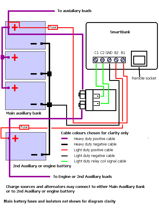
The following diagram shows a typical SmartBank installation giving split charge facilities to an auxiliary battery bank and either another auxiliary bank or an engine start battery irrespective of the type of charger or which battery bank the charge source is connected to.
This diagram applies to the SmartBank Standard AND the SmartBank Advanced but remember that SmartBank Advanced will not operate without SmartGauge.

This diagram is also available in pdf format here
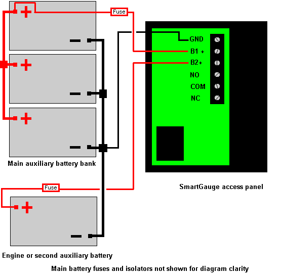
The following diagram shows the installation of SmartGauge

This diagram is also available in pdf format here
As can be seen. Both installations are incredibly simple.
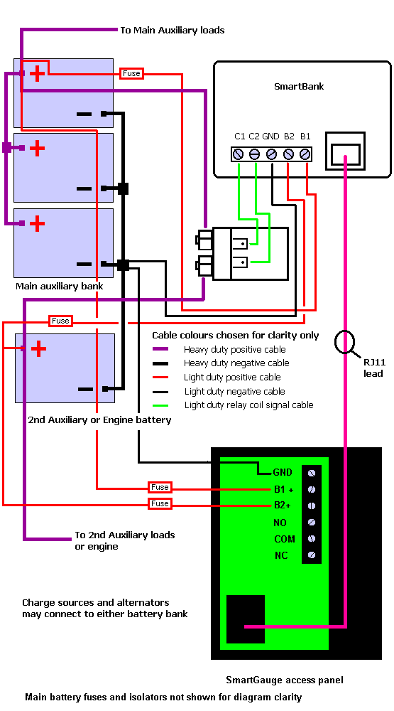
In order to operate both devices in conjunction it is necessary only to plug in the RJ11 lead between the 2 interface sockets. One on SmartGauge, one on SmartBank. That is all there is to it.
Which leads logically and simply enough onto the third schematic which is the full installation with the SmartBank and SmartGauge both installed and operating in conjunction.
Note that this diagram applies to the SmartBank Standard AND the SmartBank Advanced. The installation is identical in both cases.

This diagram is also available in pdf format here
And that really is all there is to it. Note that it is important to get Battery 1 and Battery 2 connected to the same batteries for each item of equipment. Battery 1 is the main auxiliary bank. Battery 2 is the engine start or 2nd auxiliary bank.
Page last updated 02/04/2008.
Website best viewed on a computer of some sort.