How to correctly interconnect multiple batteries to form one larger bank.
Two things I have noticed in my (more than) 20 years in this business are that:-
A. Many "specialists" simply tell you..... "do it this way, this is the correct way" without ever showing why they consider it to be the correct way, and often it isn't, which is perhaps why they couldn't show you why it is(!)
B. Some things have been done for so long, in a certain manner, that it seems they must be the best way of doing it. Otherwise why hasn't another method appeared?
Here at SmartGauge Electronics we always show you why one method is better. We don't expect you to take our word for it. We will happily use practical examples, theory, maths or whatever else it takes to show the results of various ways of doing things.
Interconnecting multiple batteries to form one larger bank is one case in point. Though in this case, newer methods have emerged over the years. Unfortunatley they still aren't perfect.
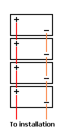
Here is a diagram showing the old way of interconnecting 4 batteries to form one larger bank. This is a method that we still see in many installations.
|
|
|
Method 1
Notice that the connections to the main installation are all taken from one end, i.e. from the end battery.
The interconnecting leads will have some resistance. It will be low, but it still exists, and at the level of charge and discharge currents we see in these installations, the resistance will be significant in that it will have a measurable effect.
Typically the batteries are linked together with 35mm cable in a good installation (often much smaller in a poor installation). 35mm copper cable has a resistance of around 0.0006 Ohms per metre so the 20cm length between each battery will have a resistance of 0.00012 Ohms. This, admittedly, is close to nothing. But add onto this the 0.0002 Ohms for each connection interface (i.e. cable to crimp, crimp to battery post etc) and we find that the resistance between each battery post is around 0.0015 Ohms.
|
|
If we draw 100 amps from this battery bank we will effectively be drawing 25 amps from each battery. Or so we think.
In actual fact what we find is that more current is drawn from the bottom battery, with the current draw getting progressively less as we get towards the top of the diagram.
The effect is greater than would be expected.
Whilst this diagram looks simple, the calculation is incredibly difficult to do completely because the internal resistance of the batteries affects the outcome so much.
However look at where the load would be connected. It is clear that the power coming from the bottom battery only has to travel through the main connection leads. The power from the next battery up has to travel through the same main connection leads but in addition also has to travel through the 2 interconnecting leads to the next battery. The next battery up has to go through 4 sets of interconnecting leads. The top one has to go through 6 sets of interconnecting leads. So the top battery will be providing much less current than the bottom battery.
During charging exactly the same thing happens, the bottom battery gets charged with a higher current than the top battery.
The result is that the bottom battery is worked harder, discharged harder, charged harder. It fails earlier. The batteries are not being treated equally.
Now in all fairness, many people say "but the difference is negligible, the resistances are so small, so the effect will also be small".
The problem is that in very low resistance circuits (as we have here) huge differences in current can be produced by tiny variations in battery voltage. I'm not going to produce the calculations here because they really are quite horrific. I actually used a PC based simulator to produce these results because it is simply too time consuming to do them by hand.
Battery internal resistance = 0.02 Ohms
Interconnecting lead resistance = 0.0015 Ohms per link
Total load on batteries = 100 amps
The bottom battery provides 35.9 amps of this.
The next battery up provides 26.2 amps.
The next battery up provides 20.4 amps.
The top battery provides 17.8 amps.
So the bottom battery provides over twice the current of the top battery.
This is an enormous imbalance between the batteries. The bottom battery is being worked over twice as hard as the top battery. The effects of this are rather complex and do not mean that the life of the bottom battery will be half that of the top battery, because as the bottom battery loses capacity quicker (due to it being worked harder) the other three batteries will start to take more of the load. But the nett effect is that the battery bank, as a whole, ages much quicker than with proper balancing.
I have to be honest now and say that when I first did this calculation in about 1990 I completely refused to believe the results. The results seemed so exaggerated. So much so that I wired up a battery bank and did the experiment for real, taking real measurements. The calculations were indeed correct.
|
|
|
Method 2
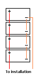
All that has changed in this diagram is that the main feeds to the rest of the installation are now taken from diagonally opposite posts.
It is simple to achieve but the difference in the results are truly astounding for such a simple modification.
The connecting leads, in fact, everything else in the installation remains identical.
Also, it doesn't matter which lead (positive or negative) is moved, Whichever is easiest is the correct one to move.
The results of this modification, when compared to the original diagram are shown below. Only that one single connection has been moved.
|
|
After this simple modification, with the same 100 amp load....
The bottom battery provides 26.7 amps of this.
The next battery up provides 23.2 amps.
The next battery up provides 23.2 amps.
The top battery provides 26.7 amps.
This is quite clearly a massive improvement over the first method. The batteries are much closer to being correctly balanced. However they are still not perfectly balanced.
How far is it necessary to go to get the matching equal?
Well, the better the quality of the batteries, the more important it becomes. The lower the internal resistance of the batteries, the more important it is to get them properly balanced.
So that now leaves the question of whether or not there is a wiring method to perfectly balance the batteries.
Before getting to that, it should be pointed out that doing the calculation is not actually required in order to arrive at the ultimate interconnection method. I simply did them to show the magnitude of the problem.
In order to get a better balancing it is simply necessary to get the number of interconnecting links as close as equal between each battery and the final loads.
In the first example the power from the bottom battery passed through no interconnecting links. The top battery passed through 6 links.
In the 2nd example (the much improved one), the power from the top and bottom battery both passed through a total of 3 links. That from the middle 2 batteries also both passed through 3 links which begs the question "why were they not therefore perfectly balanced?". The answer is that some of the links have to pass more total current and this therefore increases the voltage drop along their length.
And now we get to the correctly wired version where all the batteries are perfectly balanced.
|
|
|
Method 3
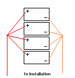
This looks more complicated.
It is actually quite simple to achieve but requires two extra interconnectng links and two terminal posts.
Note that it is important that all 4 links on each side are the same length otherwise one of the main benefits (that of equal resistance between each battery and the loads) is lost.
The difference in results between this and the 2nd example are much smaller than the differences between the 1st and 2nd (which are enormous) but with expensive batteries it might be worth the additional work. Most people (myself included) don't consider the expense and time to be worthwhile unless expensive batteries are being fitted or if the number of batteries exceeds 8.
|
|
This method isn't always so easy to install because of the required terminal posts. In some installations there is simply no room to fit these. So, thanks to a colleague, we can also present another wiring method that achieves perfect battery balancing...............
|
|
|
Method 4
And here it is.
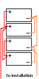
This looks odd but it's actually quite simple. What has been done here is to start with 2 pairs of batteries. Each wired in the proper "cross diagonal" method. Then each pair is wired together, again in the cross diagonal method.
Notice that for each individual battery, the current always goes through a total of one long link and one short link before reaching the loads.
This method also achieves perfect balance between all 4 batteries and may be easier to wire up in some installations. Many thanks to "smileypete" from www.canalworld.net/forums for this idea.
|
|
There really is no excuse whatsoever (apart from, perhaps, incompetence or laziness) for using the first example given at the top of this page.
The other three methods achieve much better balancing with the final two achieving perfect balancing between all four batteries.
I think I am right in saying that this is the only example I have ever come across where doing something the correct way actually looks less elegant than doing it incorrectly.
Finally, if you only have 2 batteries, then simply linking them together and taking the main feeds from diagonally opposite corners cannot be improved upon.
Once the number of batteries gets to 3 or more then these other methods have to be looked at.
With a large number of batteries it may be necessary to go to the 3rd method shown above.
Even with 8 batteries it is possible to get reasonable balancing by placing the main "take off" feeds from somewhere down the chain instead of from the end batteries. Remember, count the number of links each battery needs to run through to reach the final loads and get these as equal as possible.
Finally, if your battery bank has various take off points on different batteries, change it now! It is extremely bad practice. Not only does it mess up the battery balancing, it also makes trouble shooting very much more complicated and looks awful.
And finally, finally, we keep getting asked where the chargers should be connected to. We didn't address this question because it seemed so blatantly obvious where they should be connected that it never occurred to us that anyone might be unsure. The chargers should always be connected to the same points as the loads. Without exception.
Web site and all contents Copyright SmartGauge Electronics 2005, 2006, 2007, 2008, 2009. All rights reserved.
Page last updated 04/03/2009.
Website best viewed on a computer of some sort.


