How to increase the charge voltage of your alternator on the cheap.
If your alternator charges at, say, 13.8 volts you may want to increase this in order to get a much higher charge current into your batteries.
The two obvious solutions are to change the alternator to a later model that already charges at a higher voltage, or to fit an external alternator controller.
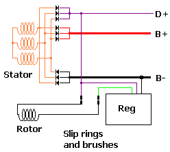
This may not be necessary. Have a look at the diagram below. This shows the schematic of an internally regulated, N-Type, -VE ground alternator. This diagram covers probably in excess of 99% of alternators currently in use.
The diagram should be self explanatory but if not...
It consists of 3 stator windings. These produce the output current at AC. This is then rectified by the two diode trios connected to the B+ and B- terminals.
The third diode trio produces a DC output at the D+ terminal to operate the warning lamp and also to provide the power to the rotor.
The regulator (Reg) compares the voltage on the D+ terminal with an internal reference and then controls the output voltage (by regulating the current in the rotor which acts as an electromagnet) to maintain the output voltage the same as the internal reference voltage.
Now in many older alternators the reference was set so that the output voltage was held at 13.6 or 13.8 volts. As described elsewhere in this website this is too low.
One way to change this would be to open up the regulator and change the voltage reference or the voltage dividers. This, obviously, is not something most people can do. However there is a much simpler way.
Instead of adjusting the voltage reference inside the regulator, what would happen if we fooled the regulator into thinking the output of the alternator was at a lower voltage than it really is?
The regulator would adjust the alternator output voltage until the new voltage we fed into the regulator was correct. So if we somehow fool the regulator into thinking the alternator output voltage is 0.6 volts lower than it really is, then the regulator will adjust the output voltage to 0.6 volts higher than this. In the case of an alternator charging at 13.8 volts, this will increase the output voltage to 14.4 volts.
A diode drops a voltage of around 0.6 volts at low currents, increasing up to around 1.2 volts at high currents. So if we use a diode at low current, it will drop just about the right voltage.
If we use a diode at a higher current then the voltage drop will be higher and therefore the output voltage of the alternator will be increased by more.
By "low current, or "high current" we mean in relation to the rating of the diode. For instance a diode rated at 3 amps would drop around 0.6 volts at 0.25 amps, increasing to around 1.2 volts at 3 amps.
Now, where we are going to put this diode in the alternator, it will have to pass the full rotor field current. This will typically be upto about 4 amps or so in a moderately sized alternator. So it would seem that we need a diode that will only drop 0.6 volts when passing around 4 amps. This would imply a very large diode, maybe 20 to 30 amp rating or so.
However this is not the case. As the batteries approach the acceptance voltage the regulator will start to reduce the field current to prevent the output voltage rising too high. So when we actually need the 0.6 volt drop, it will not be passing this higher current.
A diode of around 10 amp rating turns out to be about right. This will give a new acceptance charge voltage of about 0.6 volts higher than previously.
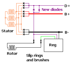
This diagram shows the position of the new additional diode in relation to the rest of the alternator wiring.
Finding the actual electrical position is left an an excercise for the student!
It should not be at all difficiult to work out by reference to the 2 diagrams on this page.
The diode on the left is the diode that raises the charge voltage. The diode on the right is there for supression purposes. It should be the same type as the other one. Not all alternators require this diode, but there is no simple way to ascertain which do and which don't so fit it anyway.
Some experimentation may be required in order to get the correct sized diode for your particular alternator.
Some notes on this matter are in order......
The diode must be able to handle the full rotor field current and must be able to dissipate the heat that will be generated within it. This will usually mean a diode with a metal heatsink. This must obviously be electrically isolated.
Selecting different sized diodes can alter the output regulation of the alternator. A smaller diode will increase the charge voltage by more than a larger diode (due to the voltage drop varying with the diode current).
It may be found that the output voltage of the alternator falls as the charge current decreases during the acceptance cycle. This cannot be helped but it can in actual fact be an advantage. Once this stage is reached the batteries are quite well charged anyway (particularly at the new higher charge voltage) and the reducing charge voltage can help reduce water loss in the batteries. Almost a gentle float reduction in charge voltage.
Some of you may want to play with different diode ratings to get different effects.
Also consider "Schottky diodes". These have a voltage drop approximately half of normal diodes and therefore the increase in charge voltage will be roughly half as much.
Many modern chargers are charging wet cell batteries at much higher voltages than previously. 14.8 to 15 volts is becoming common. This increases the charge rate and performs a mild equalisation charge. It is not recommended that such a charge voltage be used from an alternator as the alternator does not have the ability to drop to a lower float charge the same way that a dedicated charger does. However see here to add a float voltage to enable these much higher charge voltages to be utilised safely.
One last point. If you break the circuit where the new diode is fitted this will stop all charging from the alternator. Some people have actually put a switch in here to enable a much higher than normal charge voltage to be used (by putting 2 diodes in), the owner then switches the alternator off when the batteries are considered charged. Obviously if this is forgotten, the batteries may protest somewhat. Note that switching the alternator off using this method is perfectly safe and is in no way related to disconnecting the alternator output which can destroy it.
Some people may want to take this modifcation a stage further by adding a form of float voltage. If the added diodes(s) are shorted out with a manual switch, this will force the alternator back to it's original charge voltage. So the batteries could be fully charged at the higher voltage, then the alternator switched back to it's original charge voltage to reduce excess gassing of the batteries. If this switch is replaced by a relay, this relay can be controlled by the SmartGauge high voltage alarm to automatically switch down to a lower float voltage once a certain higher charge voltage is reached. This actually comes very close to how a full 3 stage external controller works. And if you already have (or are fitting) a SmartGauge then this modification is almost free! Full details are contained here.
Happy exploring.
WARNING.... Under no circumstances must this modification be done in an attempt to overcome the voltage drop introduced by split charge diodes. The voltage drop through split charge diodes varies too much as a function of the current through them. If you attempt to use this modification to compensate for this voltage drop you will either A) Achieve nothing or B) Severely overcharge your batteries or C) Achieve next to nothing followed by overcharging your batteries! It will not work.
SmartGauge Electronics accepts no liability whatsoever for any undesired consequences of carrying out this modification. If this modification is carried out, the liability lies entirely with whoever made the modification or made the decision to carry out the modification. It is the responsibility of the person carrying out the modifications to ensure the suitability of such modifications to the installation.
We wrote this page as a benefit to you. We make no profit out of it whatsoever. Please do not ask us questions about it. We will not enter into any correspondence regarding this modification. Any emails regarding this modification or asking for further details will be ignored. Sorry.
Web site and all contents Copyright SmartGauge Electronics 2005, 2006, 2007, 2008. All rights reserved.
Page last updated 21/07/2008.
Website best viewed on a computer of some sort.

